Mijia Air Conditioner Pro Eco 5-Star 1 PK Inverter FAQ
1. Q: What are the selling points of the Mijia Air Conditioner Pro Eco 5-Star 1 PK Inverter?
A: The selling points are as follows:
1. Use the air conditioner every day without worrying about electricity costs.
(1). Industry-leading energy efficiency + AI energy saving: Low-power mode allows continuous air conditioning without burden;
(2). [LOW WATT]: Multiple appliances can run simultaneously without tripping, supports wide voltage operation;
(3). [STABILIZER]: Ensures stable operation even when voltage is unstable;
2. Fast cooling without direct cold airflow
(1). Gentle airflow: Softens the air stream to prevent direct cold wind;
(2). 30s rapid cooling + Turbo mode: Instantly maximize cooling capacity with one touch;
3. Xiaomi smart ecosystem experience
(1). Xiaomi Home App control;
(2). Google or Alexa smart speaker voice control;
(3). AI engine smart control;
(4). Xiaomi smartphone infrared control;
(5). Full-link OTA upgrades.
2. Q: What are the package contents of the Mijia Air Conditioner Pro Eco 5-Star 1 PK Inverter?
A: The package contents are as follows:
1. Indoor unit and Indoor unit attachment: Indoor unit × 1, Remote Control × 1, User Manual × 1, Screw Pack × 1, AAA Battery × 2, Remote Control Holder × 1, Groove Strip for Remote Control Holder × 1, Warranty Notice × 1.
2. Outdoor unit and Outdoor unit attachment: Outdoor unit × 1, Connecting Nut × 4, Drainage Hose × 1.
3. Q: What is the appearance of the Mijia Air Conditioner Pro Eco 5-Star 1 PK Inverter?
A: The appearance is as follows:
1. Geometric shape, avoid too many decorative lines, and maintain a minimalist design language;
2. The shape is round and friendly, with a strong sense of home;
3. With a small black LED screen, it maintains the classic design image of Milook, giving the product a sense of set and recognizability.
4. Q: What are the color of the Mijia Air Conditioner Pro Eco 5-Star 1 PK Inverter?
A: The color: White + Gray.
1. Versatile color scheme, suitable for various home decor styles;
2. Neutral color palette, avoids color preference bias that can affect purchasing decisions;
3. White and gray tones, align with the Mi Home product brand identity.
5. Q: What are the packaging dimensions of the Mijia Air Conditioner Pro Eco 5-Star 1 PK Inverter?
A: Indoor unit packaging dimensions (W × H × D mm): 915 × 292 × 382. Outdoor unit packaging dimensions (W × H × D mm): 867 × 625 × 367.
6. Q: Is the Mijia Air Conditioner Pro Eco 5-Star 1 PK Inverter an inverter air conditioner?
A: Yes, the air conditioner can intelligently adjust the compressor’s operating frequency based on the actual environment, set temperature, and fan speed.
7. Q: What are the dimensions of the indoor and outdoor units for the Mijia Air Conditioner Pro Eco 5-Star 1 PK Inverter?
A: Indoor unit dimensions (W × H × D mm): 840 × 200 × 311, Outdoor unit dimensions (W × H × D mm): 804 × 551 × 311.
8. Q: What is the net weight of the Mijia Air Conditioner Pro Eco 5-Star 1 PK Inverter?
A: Indoor unit net weight: 9.9kg, Outdoor unit net weight: 21.8kg.
9. Q: What is the total weight of the Mijia Air Conditioner Pro Eco 5-Star 1 PK Inverter (net weight + packaging + accessories)?
A: Indoor unit gross weight: 11.9kg, outdoor unit gross weight: 24.4kg.
10. Q: Which APP does the Mijia Air Conditioner Pro Eco 5-Star 1 PK Inverter connect to?
A: The product supports connection to the Xiaomi Home/Mi Home APP.
11. Q: What is the networking method for the Mijia Air Conditioner Pro Eco 5-Star 1 PK Inverter?
A: It uses a 2.4G Wi-Fi module.
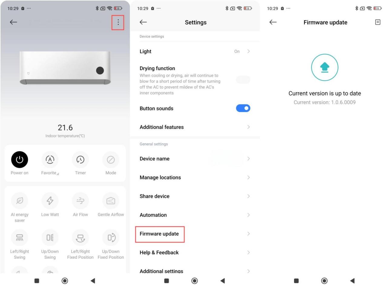
12. Q: Does the Mijia Air Conditioner Pro Eco 5-Star 1 PK Inverter support firmware upgrades?
A: Yes, the air conditioner supports remote firmware upgrades. It features full-link OTA technology, ensuring continuous updates and an ever-improving using experience.
Note:
During an OTA upgrade, the indoor unit display lights up as shown in the figure below. Do not power off or perform any operation, otherwise the upgrade can fail. During the upgrade, the air conditioner restarts, stops, and no indicator is displayed. After the upgrade is complete, the air conditioner returns to normal. The whole upgrade process takes 2-15 minutes, please wait patiently.

13. Q: What is the rated voltage of the Mijia Air Conditioner Pro Eco 5-Star 1 PK Inverter?
A: The rated voltage of the air conditioner is 220V/50Hz.
14. Q: What is the voltage fluctuation range of the Mijia Air Conditioner Pro Eco 5-Star 1 PK Inverter?
A: The air conditioner can withstand a general voltage fluctuation range of 220-240V. In extreme conditions, it can operate within a 130-265V wide voltage range, but this can affect its lifespan.
15. Q: What is the rated current of the Mijia Air Conditioner Pro Eco 5-Star 1 PK Inverter?
A: The rated current is 2.78A, and the maximum operating current is 5.1A.
16. Q: What is the power plug used by the Mijia Air Conditioner Pro Eco 5-Star 1 PK Inverter?
A: The air conditioner does not come with a power plug but includes a 1.5m power cord without a plug.
17. Q: What is the cooling power of the Mijia Air Conditioner Pro Eco 5-Star 1 PK Inverter?
A: The cooling rated power is 600W.
18. Q: What is the ambient temperature of the Mijia Air Conditioner Pro Eco 5-Star 1 PK Inverter?
A: The cooling operating temperature range is 18℃-43℃.
19. Q: Is the Mijia Air Conditioner Pro Eco 5-Star 1 PK Inverter waterproof? What is its waterproof rating?
A: The outdoor unit is waterproof (rainproof) with a waterproof rating of IPX4.
20. Q: What are the certification details of the Mijia Air Conditioner Pro Eco 5-Star 1 PK Inverter?
A: The air conditioner has the following certifications:
1. Safety certification (SNI);
2. Energy efficiency certification (SKEM);
3. Wireless certification (SDPPI).
21. Q: What is the cooling capacity of the Mijia Air Conditioner Pro Eco 5-Star 1 PK Inverter?
A: The cooling capacity is 9K Btu/h (British thermal unit).
22. Q: What is the recommended usage area for the Mijia Air Conditioner Pro Eco 5-Star 1 PK Inverter?
A: The recommended usage area is 10-15㎡.
23. Q: What is the energy efficiency rating of the Mijia Air Conditioner Pro Eco 5-Star 1 PK Inverter?
A: The air conditioner has an inverter 5-star energy efficiency rating.
24. Q: What type of refrigerant does the Mijia Air Conditioner Pro Eco 5-Star 1 PK Inverter use?
A: The air conditioner uses R32 refrigerant.
25. Q: What is the normal noise of the Mijia Air Conditioner Pro Eco 5-Star 1 PK Inverter?
A: The noise levels are as follows:
1. Indoor unit (level 1- level 4 - level 7): 23-30-38dB(A);
2. Outdoor unit: 48dB(A).
If combined with environmental noise, the actual measured noise level could be higher.
Note:
The lowest noise level of the indoor unit is 23dB(A), which is the noise level when the indoor unit is delivering the lowest airflow.
26. Q: Does the Mijia Air Conditioner Pro Eco 5-Star 1 PK Inverter use a DC motor?
A: The air conditioner uses an AC motor for the indoor unit (Model: RA15F1), and a DC motor for the outdoor unit (Model: ZKFN-37-10-1).
27. Q: Is the compressor of the Mijia Air Conditioner Pro Eco 5-Star 1 PK Inverter an inverter type?
A: Yes, the air conditioner uses a fully DC inverter compressor with the model number GSX073CKSF6JV8.
28. Q: What brand is the compressor of the Mijia Air Conditioner Pro Eco 5-Star 1 PK Inverter?
A: The air conditioner uses a compressor manufactured by Highly.
29. Q: How many rows do the condenser and evaporator of the Mijia Air Conditioner Pro Eco 5-Star 1 PK Inverter have?
A: The air conditioner has a single-row condenser and a double-row evaporator.
30. Q: How many filters does the Mijia Air Conditioner Pro Eco 5-Star 1 PK Inverter have, and what type are they?
A: The air conditioner has one indoor unit filter (at the top of the indoor unit). It is a PETK anti-mold and antibacterial filter.
31. Q: Is the filter of the Mijia Air Conditioner Pro Eco 5-Star 1 PK Inverter antibacterial and mold-resistant?
A: Yes, the filter is antibacterial and mold-resistant.
32. Q: What is the length, diameter, and material of the drainage hose for the Mijia Air Conditioner Pro Eco 5-Star 1 PK Inverter?
A: The length of the drainage hose is 2m, the diameter is Φ18mm, and the material is LDPE + EVA + anti-aging and antioxidant agents.
33. Q: What is the length of the high-pressure and low-pressure pipes in the Mijia Air Conditioner Pro Eco 5-Star 1 PK Inverter packaging?
A: The copper connection pipes are not included in the packaging. The local service provider will provide the pipes according to the actual installation requirements. High-pressure and low-pressure pipes are of the same length.
34. Q: What are the dimensions of the Mijia Air Conditioner Pro Eco 5-Star 1 PK Inverter's connection pipes (inner and outer diameters of the high-pressure and low-pressure pipes)?
A: The copper connection pipe diameters are: Φ6mm、Φ9mm.
Φ6mm pipe: Outer diameter 6.35mm, wall thickness 0.6mm or 0.7mm;
Φ9mm pipe: Outer diameter 9.52mm, wall thickness 0.7mm.
35. Q: What is the material of the connection pipes between the indoor and outdoor units of the Mijia Air Conditioner Pro Eco 5-Star 1 PK Inverter?
A: The connection pipes are made of phosphor-deoxidized seamless copper tubes, with the material number TP2M.
36. Q: What is the maximum extension length of the connection pipes for the Mijia Air Conditioner Pro Eco 5-Star 1 PK Inverter?
A: The maximum length is 10 meters. If the pipe length exceeds 7 meters, an additional 15g/m of refrigerant should be added to maintain cooling efficiency.
37. Q: What is the maximum height difference between the indoor and outdoor units of the Mijia Air Conditioner Pro Eco 5-Star 1 PK Inverter during installation?
A: The maximum height difference between the indoor and outdoor units is 5 meters.
38. Q: What type of throttling method does the Mijia Air Conditioner Pro Eco 5-Star 1 PK Inverter use?
A: The air conditioner uses a capillary tube throttling method.
39. Q: What is the air circulation volume of the Mijia Air Conditioner Pro Eco 5-Star 1 PK Inverter?
A: The air circulation volume is 620 m³/h.
40. Q: What is the maximum current of the Mijia Air Conditioner Pro Eco 5-Star 1 PK Inverter?
A: The maximum operating current is 5.1A.
41. Q: What swing modes does the Mijia Air Conditioner Pro Eco 5-Star 1 PK Inverter support?
A: It supports up/down swing and left/right swing modes.
42. Q: Does the Mijia Air Conditioner Pro Eco 5-Star 1 PK Inverter support automatic defrosting?
A: No, the air conditioner is a cooling-only device, so defrosting is not applicable.
43. Q: Does the Mijia Air Conditioner Pro Eco 5-Star 1 PK Inverter support smart dry mode?
A: Currently, it only supports standard dry mode. Smart dry mode could be available via OTA updates, so stay tuned for upgrade notifications.
44. Q: Does the Mijia Air Conditioner Pro Eco 5-Star 1 PK Inverter support battery usage statistics?
A: Yes, you can view the battery usage statistics in the Xiaomi Home App. After selecting the device, scroll down to find the battery usage statistics.
45. Q: Does the Mijia Air Conditioner Pro Eco 5-Star 1 PK Inverter support anti-direct airflow?
A: Yes, it has gentle airflow deflectors. Press the Air Flow Button to turn on the feeling function. In cooling mode, press this button to cycle through the feeling modes: gentle airflow, upward airflow, downward airflow, circulating air, and off.
46. Q: Does the Mijia Air Conditioner Pro Eco 5-Star 1 PK Inverter use an infrared or Bluetooth remote control?
A: The air conditioner uses an infrared remote control.
47. Q: What material is the screen of the Mijia Air Conditioner Pro Eco 5-Star 1 PK Inverter made of?
A: The air conditioner screen is made of PC (polycarbonate) material.
48. Q: Does the remote control of the Mijia Air Conditioner Pro Eco 5-Star 1 PK Inverter have an LED indicator?
A: No, the remote control does not have an LED indicator.
49. Q: What type of battery does the Mijia Air Conditioner Pro Eco 5-Star 1 PK Inverter remote control use?
A: The remote control uses AAA batteries.
50. Q: How much power does the Mijia Air Conditioner Pro Eco 5-Star 1 PK Inverter consume every day?
A: The actual power consumption depends on environmental factors such as room temperature and insulation, making it difficult to estimate accurately. To check real-time electricity usage, you can view the power consumption in the Xiaomi Home App.
51. Q: What smartphone brands does the Mijia Air Conditioner Pro Eco 5-Star 1 PK Inverter support for connectivity? Are there any requirements for the phone?
A: The air conditioner supports both Android and iOS devices. You need to download the Xiaomi Home/Mi Home APP to connect the air conditioner to the network and enable remote control. There are no specific requirements for the phone.
52. Q: How to clean the Mijia Air Conditioner Pro Eco 5-Star 1 PK Inverter? And how often should it be cleaned?
A: Internal cleaning is recommended once a year by a professional technician.
Exterior cleaning can be done manually.
The detailed cleaning steps are as follows:
Warning:
1. Before performing the care & maintenance on the air conditioner, make sure the air conditioner is turned off and the power supply is cut off;
2. When performing the care & maintenance on the air conditioner, avoid accidents such as tumbling or falling to avoid injury;
3. After removing the indoor unit panel, do not touch the metal fins of the heat exchanger to avoid Injury;
4. Do not clean this product with water. If water gets into the indoor unit, malfunction or electric shocks could occur;
5. Do not use chemicals or solvents such as alcohol, gasoline, lacquer thinner, polishing powder, essential balm, toothpaste or laundry detergent to clean any parts of this product to avoid damage;
6. After cleaning, make sure all parts are completely dry before installing and using them. Avoid direct sunlight.
Cleaning the air conditioner body:
Use a soft cloth or sponge dipped in clean water or diluted neutral detergent to wipe the surface of the air conditioner body.
Note:
1. Do not apply excessive force when cleaning the indoor unit panel to avoid damage;
2. Do not wipe the panel and remote control casing with wire cleaning balls, brushes, etc. to avoid damaging the casing.
53. Q: How to clean the filter of the Mijia Air Conditioner Pro Eco 5-Star 1 PK Inverter, and how often should it be cleaned?
A: It is recommended to clean the filter every three months. Once the air conditioner is connected to the network, you will receive automatic cleaning reminders from the system.
If you receive a notification, please follow these steps to clean the filter:
1. Removing the filter: Open the clips at both ends and the middle of the filter, and pull upward to remove the filter;
2. Cleaning the filter: After the filter is removed, use a vacuum cleaner to remove the dust or rinse the filter with clean water;
3. Reinstalling the filter: Align the clips with the snapping positions and reinstall the filter correctly.
Note:
1. Do not use wire mesh balls or brushes to clean the air filter to avoid damaging the filter;
2. Do not clean the unit with water to prevent water ingress, which can cause air conditioner malfunction or accidents like electric shock;
3. Do not clean the remote control with water to avoid damaging it;
4. Do not use chemicals or solvents such as alcohol, gasoline, lacquer thinner, polishing powder, menthol oil, toothpaste, or laundry powder to clean the air conditioner to prevent damage to the product.
54. Q: What type of mold prevention does the Mijia Air Conditioner Pro Eco 5-Star 1 PK Inverter offer, and what is the standard?
A: The air conditioner uses a PETK anti-mold and antibacterial filter.
It has been tested against the following mold species:
1. Aspergillus niger (CGMCC3.5487);
2. Chaetomium globosum (CGMCC3.3601);
3. Penicillium funiculosum (CGMCC3.3875).
In a standardized test environment, after 28 days of incubation, no significant mold growth was observed.
55. Q: How to find the SN on the Mijia Air Conditioner Pro Eco 5-Star 1 PK Inverter?
A: The air conditioner's SN (Serial Number) can be found in multiple locations:
1. Packaging box labels (both indoor and outdoor units);
2. Right side panel label of the indoor unit;
3. Accessory bag inside the indoor unit (SN sticker);
4. Inner label of the large handle on the outdoor unit;
56. Q: What are the key features of a split Mijia Air Conditioner Pro Eco 5-Star 1 PK Inverter?
A: The split air conditioner has the following important features:
1. Composition: It consists of an indoor unit and an outdoor unit, connected by piping and electrical wiring;
2. Types: Wall-mounted, cabinet-type, ceiling-mounted, embedded, and floor-standing;
3. Advantages:
(1). Aesthetic design, various styles, space-saving, low noise, and flexible usage;
(2). The indoor unit can be installed flexibly, and outdoor unit’s size is not limited;
(3). Produce very little noise, around 40~50dB, whereas window air conditioners generate about 60dB;
(4). Does not obstruct indoor lighting and avoids window vibrations caused by traditional window air conditioners;
(5). Easy to install and maintain;
(6). Economical, practical, and durable.
57. Q: What are the safety instructions for the Mijia Air Conditioner Pro Eco 5-Star 1 PK Inverter?
A: The safety instructions are as follows:
1. This product can only use the power supply indicated on the nameplate. Please use the specified power cord and do not change it by yourself;
2. Do not connect the grounding wire of the power supply to a gas tank or water pipe. insufficient grounding could result in electric shock;
3. Make sure that the wiring harness, drainage hose, and compressor pipe are connected correctly. Improper connection could cause the air conditioner not to function or reduce performance after some time or even have problems of water leakage, electrical leakage, fluorine leakage, electric shock, or fire accidents;
4. Use the button to turn the product on or off instead of plugging or unplugging the power plug during daily use. Please turn off the product and unplug the power plug when not in use for a long time;
5. When the ambient humidity is high, please increase the fan speed or adjust the air guide blade angle to the maximum using the wind direction button to prevent water droplets from falling;
6. Do not install the air conditioner in places where flammable or explosive gases could leak, where the environment is humid, or where electromagnetic interference is significant. The indoor unit of this air conditioner is not waterproof, so do not use it in humid environments such as laundry rooms or bathrooms;
7. When indoor ventilation equipment is used together with indoor heating equipment or gas stoves, it should be ensured to avoid hypoxic accidents caused by insufficient ventilation;
8. Do not blow the air from the air conditioner directly to animals or plants otherwise, it could cause adverse effects;
9. When cleaning the air conditioner, be sure to turn it off and cut off the power supply, and make sure that the air conditioner has completely stopped before operating;
10. Do not poke your fingers or sticks into the exhaust inlet or exhaust outlet of the air conditioner. Otherwise, it could cause damage to the air conditioner or even personal injury;
11. Do not place any objects on the outdoor unit and check its mounting bracket frequently. If there is any damage, repair it in time; otherwise, the outdoor unit could fall and cause injury;
12. If any abnormality in the air conditioner (such as a burnt smell) is found, turn the air conditioner off, cut off the power supply immediately, and contact the after-sales service center;
13. For safety's sake, cut off the power supply before touching the air conditioner;
14. Do not install the air conditioner in special places such as ships or vehicles.
58. Q: What to do if feeling an electric tingling sensation when touching the Mijia Air Conditioner Pro Eco 5-Star 1 PK Inverter?
A: For your safety, please avoid touching the indoor and outdoor units while the air conditioner is operating. If you accidentally touch the outdoor unit and feel a tingling sensation, please contact a professional technician to properly connect the air conditioner's ground wire to prevent electric shock or other accidents.
59. Q: What is the dehumidification capacity of the Mijia Air Conditioner Pro Eco 5-Star 1 PK Inverter?
A: The dehumidification capacity of the air conditioner has not been tested yet.
60. Q: How to check the production date of the Mijia Air Conditioner Pro Eco 5-Star 1 PK Inverter?
A: The air conditioner's production year/month information can be found on the labels of the air conditioner's indoor and outdoor units.
61. Q: What do the letters and numbers in the Mijia Air Conditioner Pro Eco 5-Star 1 PK Inverter mean?
A: The model is ASC-09WO/N1C5-ID.
The meanings of the letters and numbers are as follows:
1. Category code: A - Air Conditioner;
2. Type code: S (Split);
3. Heating and cooling code: C - Cooling only;
4. Capacity code: 09 - 9000BTU;
5. Indoor unit code: W - Wall-mounted;
6. Outdoor unit code: O - Outdoor unit;
7. Series and product iteration code: N1 - Super energy-saving series;
8. Refrigerant code: C - R32 refrigerant;
9. Energy efficiency level: 5 - 5-star;
10. Energy efficiency standard code: ID - Indonesia.
Function usage
1. Q: How to connect the Mijia Air Conditioner Pro Eco 5-Star 1 PK Inverter to the Xiaomi Home/Mi Home APP?
A: Install the Xiaomi Home/Mi Home APP and log in to your account, and follow the steps below to configure:
1. First connect your phone to your home Wi-Fi, then open the Xiaomi Home/Mi Home APP, tap [+] at the upper right corner to enter the [Add device] interface, tap the name of the searched air conditioner product to enter the Wi-Fi configuration interface;
2. Follow the on-screen prompts to proceed to the next step until the message "Device added successfully" is displayed.
Note:
1. You can install the Mi Home APP using an Android phone through nearby devices or add it manually. After installing the Xiaomi Home/Mi Home APP using an iOS phone, tap the [+] icon at the upper right corner of the homepage to manually select devices to add, or tap the Bluetooth icon at the upper right corner to select new products scanned for addition;
2. To update the indoor and outdoor units, you can tap the three dots icon at the upper right corner, and select [Firmware update] to check for updates.
2. Q: How to reset the Wi-Fi of the Mijia Air Conditioner Pro Eco 5-Star 1 PK Inverter?
A: Simultaneously press and hold the light and sleep buttons for more than three seconds to reset the Wi-Fi.
3. Q: How to adjust the temperature of the Mijia Air Conditioner Pro Eco 5-Star 1 PK Inverter?
A: In cooling mode, the temperature adjustment range is 16℃ to 31℃. You can adjust the air conditioner temperature using [+] and [-] buttons on the remote control, with each press adjusting the temperature by 0.5℃.
4. Q: How to control the Mijia Air Conditioner Pro Eco 5-Star 1 PK Inverter with the remote control?
A: The remote control uses infrared technology. To use it, simply point the remote at the front of the air conditioner (the display screen).
Note:
1. The infrared receiver is located behind the display screen, which has some light-transmitting properties;
2. The effective remote control range is less than 8 meters, with an approximately 45° range on both sides.
5. Q: How to install the batteries in the remote control of the Mijia Air Conditioner Pro Eco 5-Star 1 PK Inverter?
A: The method for installing the batteries is as follows:
1. Press the upper groove of the battery cover with your finger and slide the cover down (see the left image below);
2. Open the battery cover and insert two AAA batteries into the battery compartment in the direction shown in the right image below. Then, securely close the battery cover.
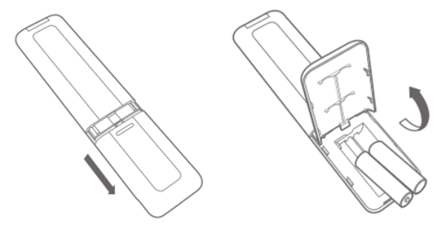
Note:
When installing, please pay attention to the correct polarity of the batteries. Incorrect installation will prevent the remote control from working properly. Do not forcefully pull or remove the battery cover.
6. Q: How to upgrade the firmware version of the Mijia Air Conditioner Pro Eco 5-Star 1 PK Inverter?
A: When a new version is available, you will see an update notification in the three-dot icon at the upper right corner of the device card interface. The firmware is continuously updated and optimized, so upgrading to the latest version is recommended for a better using experience.
7. Q: How to install the Mijia Air Conditioner Pro Eco 5-Star 1 PK Inverter?
A: The air conditioner installation requires a certain level of expertise, so it is recommended to schedule an on-site installation service instead of installing it yourself.
8. Q: How to set the Mijia Air Conditioner Pro Eco 5-Star 1 PK Inverter to turn on and off at a scheduled time?
A: When the air conditioner is turned on, the remote control can be used to set a turn-off timer. When the air conditioner is turned off, the remote control can be used to set a turn-on timer. Press the timer button to enter the timer mode, and then press [+] or [-] to adjust the time. The timer is set successfully if there is no operation for two seconds.
Note:
The turn-on timer defaults to the mode, temperature, fan speed, and swing modes used before the last shutdown. If you would like to use the functions during the next turn-on, you can set the mode, temperature, fan speed, and swing modes as needed when the air conditioner is running, and then turn off the air conditioner and set the turn-on timer.
There are 3 ways to control the scheduled on/off time through the Xiaomi Home/Mi Home APP, which is explained as follows:
1. Using the Timer function on the air conditioner’s homepage, you can use [Timer] and select [Power on timer] or [Power off timer] to set the air conditioner;
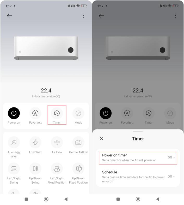
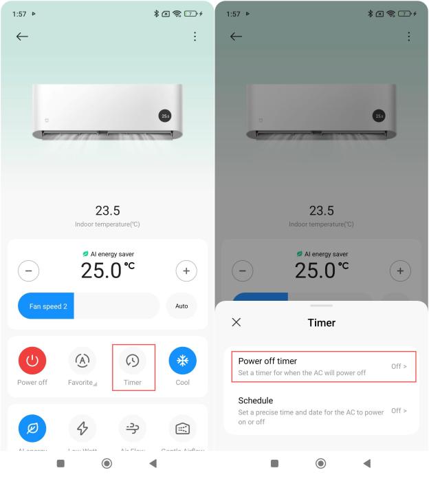
Note:
When the air conditioner is turned off, you can set a timer to turn it on, and when the air conditioner is turned on, you can set a timer to turn it off.
2. On the device card interface, you can use [Timer] and select [Schedule] to set the air conditioner to turn on and off at a specified time;
Note:
This method has both "on" and "off" times. The air conditioner will automatically turn on at the specified start time and turn off at the specified end time.
3. Using smart scenes, you can create an automation rule in the [Automation] section of the Xiaomi Home/Mi Home APP to schedule the air conditioner to turn on or off at specific times.
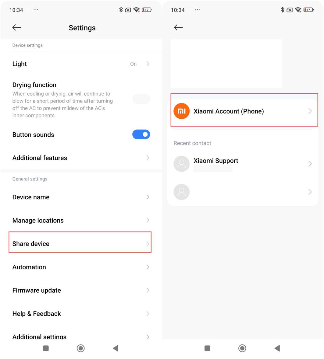
9. Q: How to enable multiple people to control the Mijia Air Conditioner Pro Eco 5-Star 1 PK Inverter?
A: After connecting and binding the air conditioner with the Mi Home/Mi Home APP, you can share it with family members.
The setting path is as follows:
Open the Xiaomi Home/Mi Home APP >> tap the device card >> tap the three-dot icon at the upper right corner >> select [Share device] >> [Xiaomi Account (Phone)].
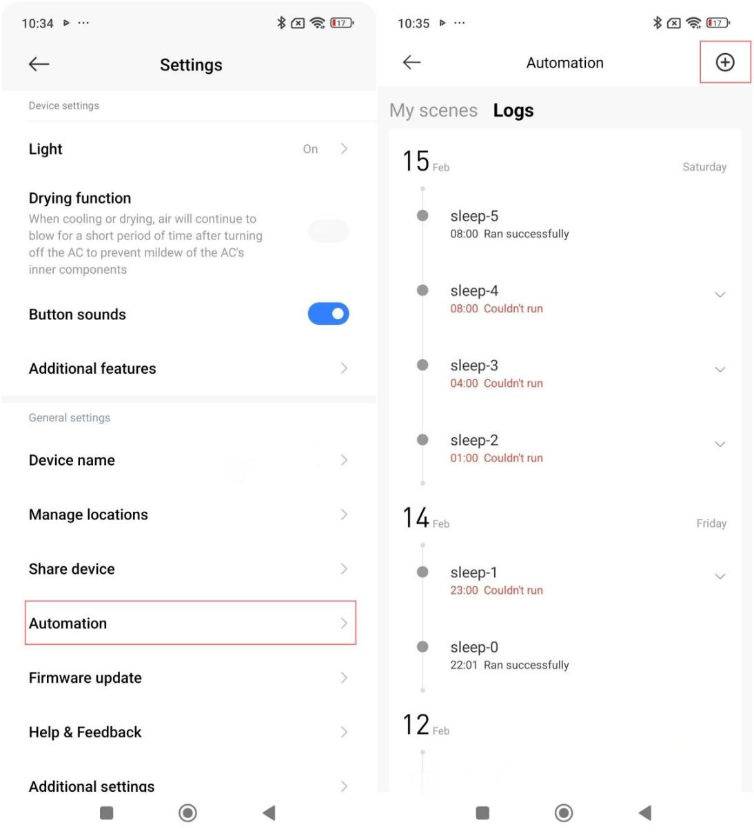
10. Q: How to achieve linkage between the Mijia Air Conditioner Pro Eco 5-Star 1 PK Inverter and other devices?
A: The air conditioner supports setting smart scenes and can be linked with other devices.
The setting path is as follows:
Open the Xiaomi Home/Mi Home APP >> tap the three-dot icon at the upper right corner of the device interface >> select [Automation] >> tap [+].
11. Q: How to adjust the operating mode of the Mijia Air Conditioner Pro Eco 5-Star 1 PK Inverter?
A: Press the mode button to switch modes in the sequence cooling mode, dry mode, and fan mode.
12. Q: How to adjust the fan speed of the Mijia Air Conditioner Pro Eco 5-Star 1 PK Inverter?
A: Press the Fan Speed button to adjust the speed: automatic, quiet (level 1), low (level 2), low-medium (level 3), medium (level 4), medium-high (level 5), high (level 6), turbo (level 7).
Note:
The fan speed is not adjustable in dry mode.
13. Q: How to enable the child lock function of the Mijia Air Conditioner Pro Eco 5-Star 1 PK Inverter?
A: Simultaneously press and hold "+" and "-" on the remote control for more than three seconds to enable or disable the child lock function.
14. Q: How use the Auto clean function of the Mijia Air Conditioner Pro Eco 5-Star 1 PK Inverter?
A: You can use the air conditioner's Auto clean function as follows:
When the air conditioner is turned off, simultaneously press and hold the LOW WATT button and the timer button for more than three seconds to enable the Auto clean function. The remote control will show automatic cleaning, and the display of the air conditioner is blinking. Then the air conditioner will run for about 40 minutes, and automatically exit the Auto clean function and shut down.
Note:
1. The duration displayed on the remote control and the air conditioner display will vary;
2. There can be noise, breeze, and cold air during the Auto clean operation, which is normal;
3. When the ambient temperature is too high or too low, the air conditioner will automatically activate the protection function, which could cause the Auto clean function to be exited or fail to start;
4. Auto clean can only clean the heat exchanger.
15. Q: How to adjust the air direction of the Mijia Air Conditioner Pro Eco 5-Star 1 PK Inverter?
A: Press the Up/Down Swing and Left/Right Swing buttons to adjust the air direction.
Press the Left/Right Swing button to turn the horizontal oscillation on or off.
Press the Up/Down Swing button to turn the vertical swing function on or off.
16. Q: How to adjust the screen brightness of the Mijia Air Conditioner Pro Eco 5-Star 1 PK Inverter?
A: The air conditioner supports turning on or off the display by pressing the light button.
17. Q: How to turn on/off the Mijia Air Conditioner Pro Eco 5-Star 1 PK Inverter?
A: Press the on/off button to turn the air conditioner on or off.
18. Q: Where is the best location to install an air conditioner? What should be noted?
A: Air conditioner installation requires a certain level of expertise. It is recommended that you schedule an on-site installation service rather than installing it yourself.
The main installation locations are as follows:
1. Outdoor Unit Location Selection
(1). Avoid exposure to direct sunlight or strong airflow;
(2). Keep away from heat sources, steam sources, and places with flammable gas leakage and smoke;
(3). Select a place that is not exposed to rain and has good ventilation;
(4). Choose a place where the air outlet and operating noise of the air conditioner will not disturb other people or animals or plants;
(5). Make sure the installation space is not smaller than the requirements;
(6). Make sure the air outlet is open and unobstructed to avoid affecting the performance;
(7). The outdoor unit shall not occupy public sidewalks. If the outdoor unit is installed along buildings on both sides of the road, the distance from the bottom of the outdoor unit mounting bracket to the ground shall be greater than 25cm. On the condition that the outdoor unit mounting bracket does not affect the public passages, the distance from the bottom of the outdoor unit to the ground shall be greater than 25cm;
(8). To ensure the room temperature regulation effect, it is recommended to remove the obstructions like the shutter in front of the outdoor unit when installing. If such obstructions cannot be removed, the air outlet of the outdoor unit shall be placed as close to the shutter as possible;
(9). The installation location shall be firm and reliable, otherwise it will increase operating noise and vibration and bring danger.
2. Indoor Unit Location Selection
(1). Avoid direct sunlight;
(2). There are no obstacles at the air inlet and outlet to maintain good air circulation;
(3). It’s convenient for the drainage hose to drain water;
(4). The distance to radio devices (such as TV or radio) is greater than 1m;
(5). The air conditioner shall be installed on a wall that can bear the weight of the indoor unit and does not increase the operating noise and vibration;
(6). The minimum clearance between the auxiliary electric heating air conditioners and the surfaces of combustible materials is 1.5m;
(7). The auxiliary electric heating components are assembled and fixed in the indoor unit evaporator. They are ceramic PTC electric heating elements. The input power can be found in the "PTC" on the nameplate (Input Power for the Auxiliary Electric Heater).
Note:
1. Models without "Input Power for the Auxiliary Electric Heater (PTC)" on the nameplate do not have this component;
2. For the best performance, please make sure to install the indoor and outdoor units according to the spacing shown in the User Manual.
19. Q: How to enable the sleep function of the Mijia Air Conditioner Pro Eco 5-Star 1 PK Inverter?
A: To enable the sleep function, please refer to the following steps:
1. In cooling mode, press the sleep button to turn the sleep function on or off. When sleep function is on, the sleep icon appears on the remote control display;
2. In sleep mode, the air conditioner will automatically adjust the temperature according to the sleep curve.
Note:
The sleep mode can be turned on only in cooling mode.
20. Q: How to use the dry mode of the Mijia Air Conditioner Pro Eco 5-Star 1 PK Inverter?
A: Press the mode button on the remote control until the dry mode icon appears.
21. Q: How to restore the Mijia Air Conditioner Pro Eco 5-Star 1 PK Inverter to factory settings?
A: Restoring factory settings:
Within five minutes of the air conditioner connecting to power (make sure it is turned off), quickly press the light button on the remote control six times in five seconds, and then the air conditioner makes a buzzer sound for two seconds. Disconnect the power and reconnect the power, and the factory settings will be restored.
Note:
1. When restored to the factory settings, the air conditioner will delete all data including but not limited to the set temperature.fan speed, timing information, function switches, and accumulated electricity consumption;
2. It is not recommended to restore the factory settings unless necessary, so as not to affect the experience of some functions. For example, the accumulated electricity consumption value will be significantly different from the actual electricity consumption value.
22. Q: What should be aware of when using the Mijia Air Conditioner Pro Eco 5-Star 1 PK Inverter?
A: Please pay attention to the following points when using the air conditioner:
1. Check the operating conditions: The cooling mode operates within a temperature range of 18℃~43℃. If the ambient temperature is too high or too low, the unit will shut down for protection;
2. Safety precautions: For safety-related usage guidelines, please refer to the user manual.
23. Q: How to use the drying function of the Mijia Air Conditioner Pro Eco 5-Star 1 PK Inverter?
A: The air conditioner supports the drying function, you can enable the drying function in the Xiaomi Home/Mi Home APP.
The path: Open the Xiaomi Home/Mi Home APP >> tap the three-dot icon at the upper right corner >> select [Drying function].
24. Q: How to use the AI function of the Mijia Air Conditioner Pro Eco 5-Star 1 PK Inverter?
A: Follow these steps to use the AI features of the air conditioner:
1. Voice control: Google Home APP or Amazon Alexa APP:
(1). Download and log in to the Google Home APP or Amazon Alexa APP;
(2). Connect (bind) the air conditioner device in the voice assistant. If you have a Google or Alexa smart speaker at home, you can also bind the air conditioner to the speaker;
(3). Once connected to the internet, you can use voice commands to control the air conditioner.
2. AI energy saving: Achieves long-term energy savings and improves environmental adaptability through cloud-based deep learning algorithms.
After the air conditioner is connected to the network, it automatically detects the surrounding environment and location. It intelligently selects the appropriate mode based on the scenario. For example, if the environment temperature is 40℃ and the room size is 16m², the air conditioner will prioritize rapid cooling.
While in cooling mode, enabling AI energy saver mode (button name can vary) in the Xiaomi Home/Mi Home APP ensures precise and stable temperature control, achieving long-term energy efficiency.
Note:
Google Home APP and Amazon Alexa APP are expected to be launched at the end of May.
25. Q: How to check the service life of the filter of the Mijia Air Conditioner Pro Eco 5-Star 1 PK Inverter?
A: The air conditioner has no filter element, and the filter will not be damaged in general. Just follow the prompts to clean it.
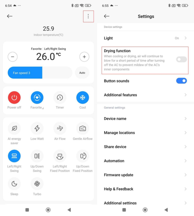
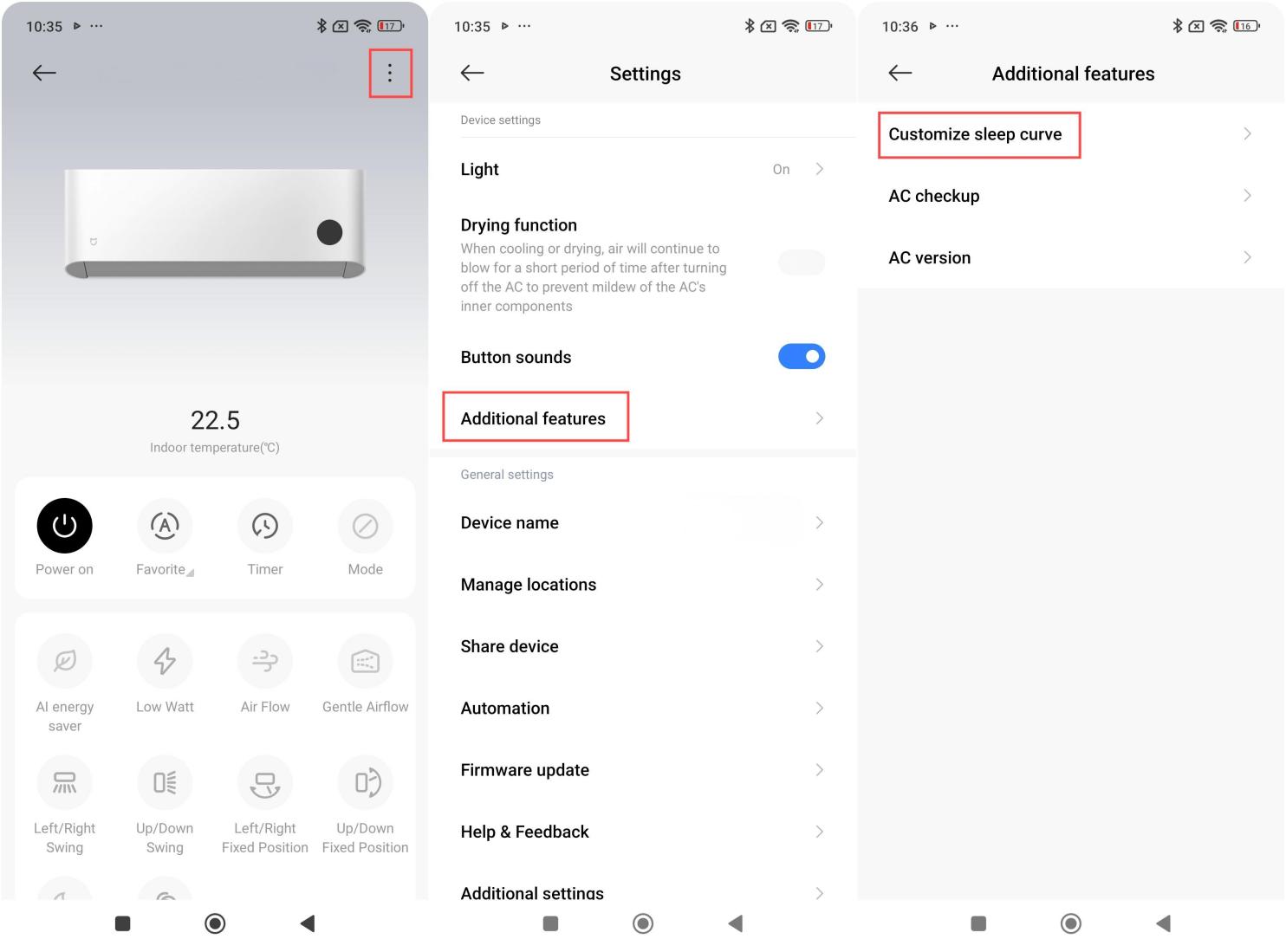
26. Q: How to check the sleep curve of the Mijia Air Conditioner Pro Eco 5-Star 1 PK Inverter?
A: To check the sleep curve, please refer to the following steps:
1. Open the Xiaomi Home/Mi Home APP and find the device you want to check the sleep curve;
2. Tap the three-dot icon at the upper right corner to enter the settings page, select [Additional features], then choose [Customize sleep curve] to view it.
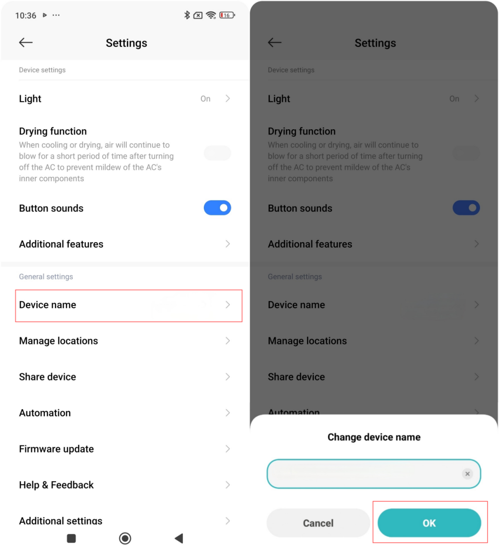
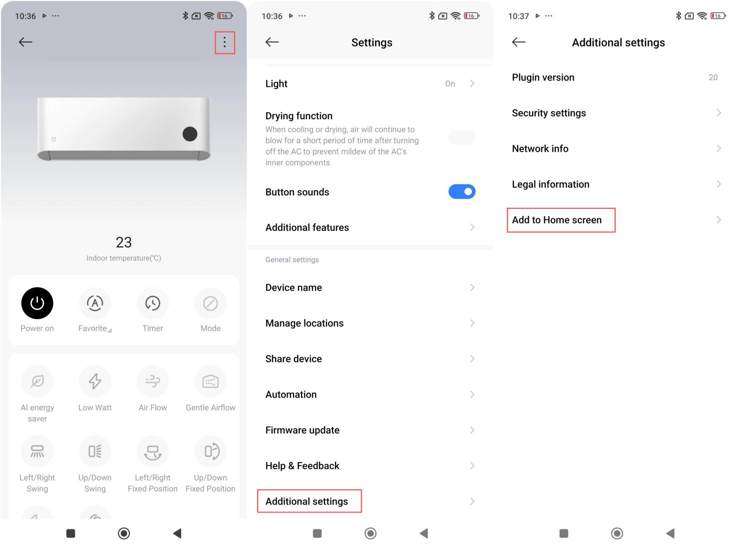
27. Q: How to change the device name of the Mijia Air Conditioner Pro Eco 5-Star 1 PK Inverter?
A: To change the device name, please refer to the following steps:
1. Open the Xiaomi Home/Mi Home APP and find the device you want to change the name;
2. Tap the three-dot icon at the upper right corner to enter the settings, and select [Device name], then make the changes;
3. Confirm that the modified name has been saved successfully.
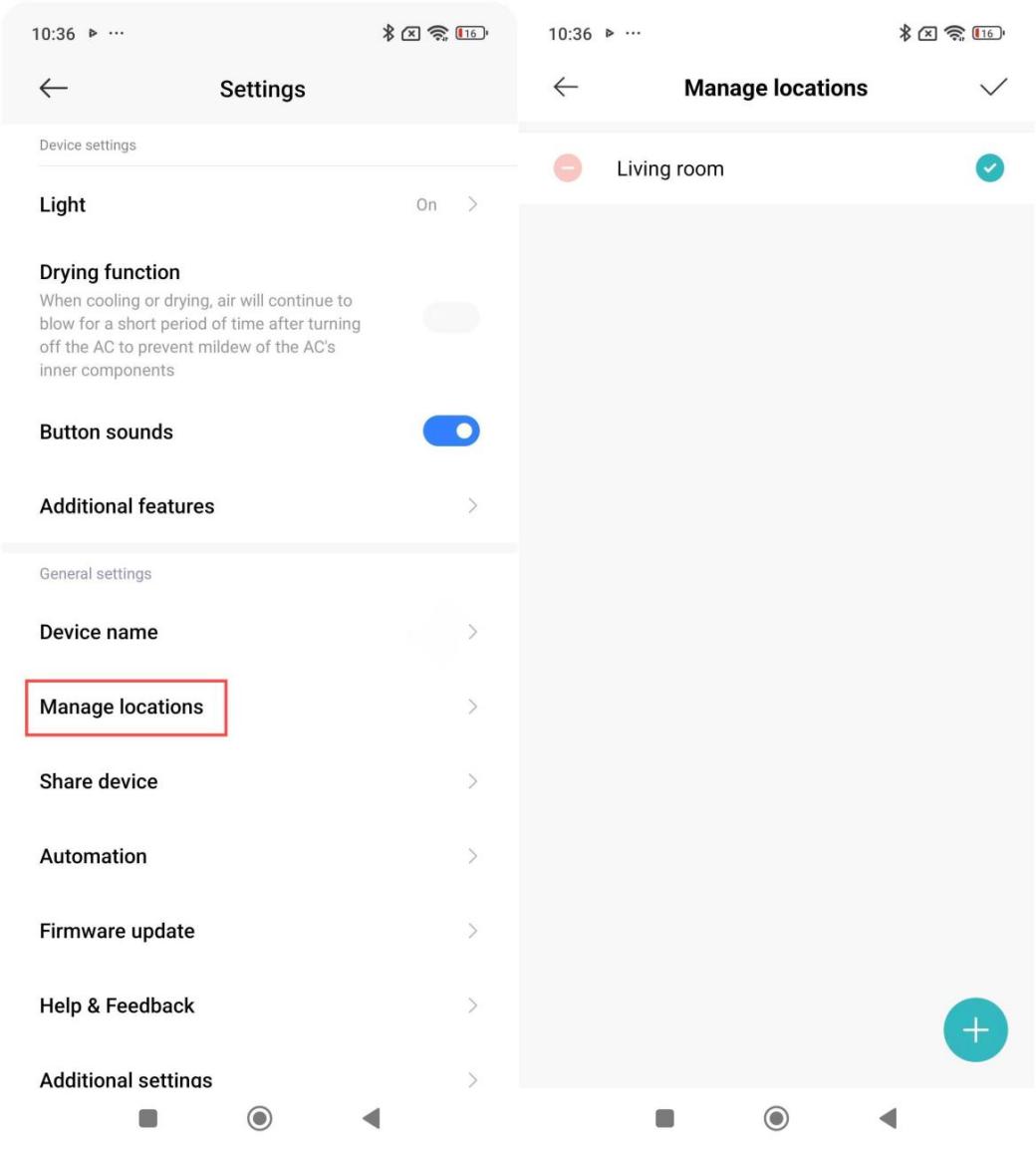
28. Q: How to manage the location of the Mijia Air Conditioner Pro Eco 5-Star 1 PK Inverter?
A: To manage the air conditioner's location, please refer to the following steps:
1. Open the Xiaomi Home/Mi Home APP and find the device you want to manage;
2. Tap the three-dot icon at the upper right corner to enter the settings, and select [Manage locations], then proceed with the management.
29. Q: How to add the Mijia Air Conditioner Pro Eco 5-Star 1 PK Inverter to Home screen?
A: Please follow these steps to add the air conditioner to Home screen:
1. Open the Xiaomi Home/Mi Home APP and find the device you want to add as a desktop shortcut;
2. Tap the three-dot icon at the upper right corner to enter the settings;
3. In the settings page, find the [Additional settings] option and tap to enter;
4. Select [Add to Home screen] to complete the process.
30. Q: What is the most energy-efficient temperature setting for the Mijia Air Conditioner Pro Eco 5-Star 1 PK Inverter?
A: Energy efficiency depends on factors such as room size and insulation. For a balance between comfort and energy savings, setting the air conditioner to 26℃ in cooling mode is optimal.
31. Q: How to bind the Mijia Air Conditioner Pro Eco 5-Star 1 PK Inverter to a smart band? How to use the smart band to control the air conditioner?
A: The air conditioner does not currently support binding with a smart band.
32. Q: Does the Mijia Air Conditioner Pro Eco 5-Star 1 PK Inverter have a memory function? (Will it resume the previous settings after a power outage?)
A: The air conditioner has a power-off memory function, but it only records and saves the device's operating state prior to the last power outage. It will not automatically turn the air conditioner back on when power is restored, you still needs to manually turn it on.
33. Q: How to use the Mijia Air Conditioner Pro Eco 5-Star 1 PK Inverter's Auto clean function?
A: With the air conditioner turned off, press the LOW WATT and Timer buttons on the remote control simultaneously. After 3 seconds, the Auto clean mode will activate. The Auto clean process lasts approximately 40 minutes.
34. Q: How to use the low watt function on the Mijia Air Conditioner Pro Eco 5-Star 1 PK Inverter?
A: In cooling mode, press the LOW WATT button to turn on, off or cycle through the LOW-WATT levels: level 1, level 2, level 3, level 4, level 5, level 6, and off.
35. Q: How to turn on/off the Mijia Air Conditioner Pro Eco 5-Star 1 PK Inverter?
A: To turn the air conditioner on or off, please refer to the following methods:
1. Point the remote control at the air conditioner's display screen and press the power button to turn the unit on or off;
2. After the air conditioner is connected to the network, you can also use the Xiaomi Home/Mi Home APP to power the air conditioner on or off by tapping the power icon;
3. For scheduled power on/off, both the remote control and the Xiaomi Home/Mi Home APP have a timer button that allows you to set the on/off schedule.
36. Q: What modes does the Mijia Air Conditioner Pro Eco 5-Star 1 PK Inverter have?
A: The modes of the air conditioner are cooling mode, dry mode and fan mode.
37. Q: Do the filters of the Mijia Air Conditioner Pro Eco 5-Star 1 PK Inverter need to be replaced regularly?
A: The filter does not need to be replaced unless it is damaged or deformed.
38. Q: How to clean the evaporator of the Mijia Air Conditioner Pro Eco 5-Star 1 PK Inverter?
A: After the air conditioner is powered off, remove the front panel of the indoor unit. First, spray the cleaner onto the evaporator fins of the indoor unit. After 5-10 minutes, rinse it thoroughly with clean water. Be careful during the cleaning process to avoid water entering the electrical control box or display board terminals, as this could cause electrical faults.
If you use the Auto Clean mode for cleaning, you can follow the instructions for the Auto Clean mode.
39. Q: Can the direction of the pipes on the indoor unit of the Mijia Air Conditioner Pro Eco 5-Star 1 PK Inverter be changed?
A: The direction of the indoor unit pipes can be adjusted: left-side exit, rear exit, or right-side exit.
40. Q: Why is the filter of the Mijia Air Conditioner Pro Eco 5-Star 1 PK Inverter located on the top? What are its advantages?
A: The integrated filter design simplifies product development and meets the need for top air intake to block dust.
Advantages:
1. The filter is easy to remove, and can be detached with a single operation without disassembling other parts;
2. The integrated filter does not need to be disassembled for cleaning, making maintenance more convenient.
41. Q: How to use the Turbo mode of the Mijia Air Conditioner Pro Eco 5-Star 1 PK Inverter?
A: After the air conditioner is powered on and operating normally, press the Turbo button on the remote control to turn the turbo airflow on or off. For air conditioners that are connected to the network, Turbo mode can also be turned on or off through the Turbo icon in the Xiaomi Home/Mi Home APP.
42. Q: How does the Turbo mode of the Mijia Air Conditioner Pro Eco 5-Star 1 PK Inverter work?
A: The Turbo mode maximizes the air conditioner's cooling capacity for rapid cooling. When Turbo mode is activated, the system adjusts the compressor, fan, and other components to run at their maximum frequency and speed, achieving quick cooling.
43. Q: How use the gentle airflow function on the Mijia Air Conditioner Pro Eco 5-Star 1 PK Inverter?
A: Press the air flow button to cycle through the feeling modes: gentle airflow, upward airflow, downward airflow, circulating air, and off. When the wind feeling stays at "gentle airflow", it indicates the gentle airflow feeling function is active.
44. Q: How does the gentle airflow function on the Mijia Air Conditioner Pro Eco 5-Star 1 PK Inverter work?
A: The air conditioner is equipped with a gentle airflow deflector. When the gentle airflow mode is activated, the left and right oscillating motors move the deflector to a position perpendicular to the airflow direction. The holes reserved on the left and right deflectors scatter the airflow, creating a soft airflow effect.
A: The OTA upgrade will be rolled out progressively starting from September 25, 2025.
Here are the update contents of the Mijia Air Conditioner Pro Eco 5-Star 1 PK Inverter:
1. Multiple cooling modes;
2. Adjustable noise levels;
3. Smart anti-condensation;
4. Cloud-based filter cleaning reminder.
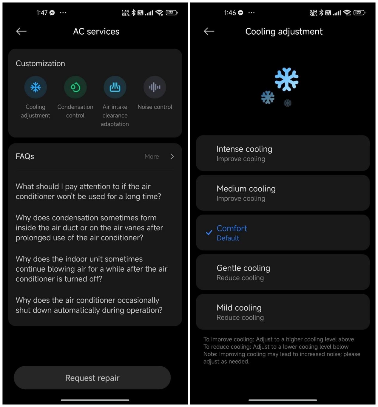
48. Q: What are the cooling modes of the Mijia Air Conditioner Pro Eco 5-Star 1 PK Inverter after OTA update?
A: After the OTA update, there are multiple cooling modes added to the Mijia Air Conditioner Pro Eco 5-Star 1 PK Inverter. The cooling modes include Intense cooling, Medium cooling, Comfort, Gentle cooling, and Mild cooling.
To improve cooling, please adjust the cooling mode to a higher cooling level above.
To reduce cooling, please adjust the cooling mode to a lower cooling level below.
Note:
Improving cooling may lead to increased noise, please adjust as needed.
49. Q: What is filter cleaning reminder on the Mijia Air Conditioner Pro Eco 5-Star 1 PK Inverter?
A: The Cloud-based filter cleaning reminder is calculated based on the difference between the air outlet temperature and the air inlet temperature, pipe temperature and other parameters detected by the air conditioner, not based on the number of days or hours of operation.
Troubleshooting
1. Q: What to do if the Mijia Air Conditioner Pro Eco 5-Star 1 PK Inverter cannot connect to the Xiaomi Home/Mi Home APP?
A: If the air conditioner cannot connect to the APP, please refer to the following steps to troubleshoot:
1. Check if the air conditioner is turned on and in connection mode. Unplug the power for 10 seconds and then plug it back in, or reset the air conditioner’s Wi-Fi and try reconnecting again;
2. Ensure that the connected Wi-Fi is a 2.4G network, as the air conditioner only supports 2.4G Wi-Fi and does not support 5G Wi-Fi;
3. Ensure the router is not too far from the air conditioner and that the router is functioning properly with internet access;
4. Make sure the router’s SSID and password do not contain Chinese characters or special symbols, and verify that the SSID and password are entered correctly;
5. Try manually setting up a mobile hotspot to see if the issue is related to the router's network;
6. Update the Xiaomi Home/Mi Home APP to the latest version and follow the step-by-step instructions in the APP to connect the air conditioner.
If the issue persists after following these steps, please request the after-sales service center for further inspection.
2. Q: What to do if the firmware upgrade of the Mijia Air Conditioner Pro Eco 5-Star 1 PK Inverter fails in the Xiaomi Home/Mi Home APP?
A: If the firmware upgrade fails, please follow these steps:
1. Update the Xiaomi Home App to the latest version and try again;
2. Check if the Wi-Fi network is working properly and has internet access;
3. Try connecting to a different network and see if the upgrade can proceed successfully;
4. During the firmware upgrade process, do not exit the upgrade interface or close the APP to ensure the update completes properly;
5. If the above steps do not resolve the issue, please contact the after-sales service center for assistance.
3. Q: What to do if the Mijia Air Conditioner Pro Eco 5-Star 1 PK Inverter stops working during cooling?
A: If the air conditioner stops working, please troubleshoot as follows:
1. Check whether the room temperature has reached the set temperature. If so, the air conditioner will automatically reduce its frequency and fan speed;
2. Please enable the LOW WATT mode and check if the device can operate properly;
3. Check if an error code is displayed. Some of the error codes are the protection codes. If so, wait for a while, and the unit should resume operation automatically;
4. If the above steps do not resolve the issue, please contact the after-sales service center for inspection.
4. Q: What are the different statuses of the Wi-Fi indicator on the Mijia Air Conditioner Pro Eco 5-Star 1 PK Inverter?
A: The Wi-Fi indicator statuses of the indoor unit are as follows:
1. Wi-Fi not connected (within 30 minutes): Wi-Fi indicator flashes;
2. Wi-Fi not connected (over 30 minutes): Wi-Fi indicator turns off while the unit is on;
3. Wi-Fi connected: Wi-Fi indicator stays on while the unit is on;
4. Standby mode: Wi-Fi indicator stays on while the unit is off.
5. Q: What to do if the Mijia Air Conditioner Pro Eco 5-Star 1 PK Inverter's Wi-Fi indicator displays abnormally?
A: Please check if the air conditioner is properly connected to the network. If it cannot connect, please request the after-sales service center for inspection.
6. Q: What to do if the Mijia Air Conditioner Pro Eco 5-Star 1 PK Inverter cannot adjust the temperature?
A: If the air conditioner fails to adjust the temperature, Please follow these troubleshooting steps:
Using the remote control:
1. Check if the remote control batteries are functional. Replace them if necessary;
2. Ensure the remote control is displaying correctly and that other buttons are working;
3. Please check if the air conditioner is in LOW WATT mode or sleep mode, as these modes will limit the temperature adjustment function;
4. Confirm that the air conditioner receives the remote control signals (listen for a beep sound);
5. Please turn off the air conditioner for 3-5 minutes and then restart it to see if the issue is resolved;
6. If the issue remains unresolved, please contact the after-sales service center.
Using the Xiaomi Home/Mi Home APP:
1. Disconnect the Xiaomi Home/Mi Home APP completely (delete the device from the APP and reset the air conditioner Wi-Fi), then try using only the remote control;
2. Check if other remote-controlled devices in your home are interfering with the air conditioner.
3. If the issue still occurs after troubleshooting, it could be a hardware issue, and the after-sales service is recommended;
4. If the issue disappears, it is due to smart settings in the Xiaomi Home App (such as sleep curve or LOW WATT mode). Please reset the Wi-Fi and clear historical data in the APP.
If neither the remote control nor the APP can control the air conditioner, please request after-sales service for inspection.
7. Q: What to do if the Mijia Air Conditioner Pro Eco 5-Star 1 PK Inverter’s airflow temperature is not appropriate?
A: If the airflow temperature is not appropriate, please follow these troubleshooting steps:
1. Check the air conditioner’s mode settings to ensure the appropriate mode (cooling or fan mode) for the current season is selected;
2. Adjust the temperature setting according to your comfort level, increasing or decreasing the set temperature as needed;
3. Modify the fan speed to improve airflow comfort;
4. Clean the air filter and check if the unit needs maintenance.
8. Q: What to do if the airflow direction of the Mijia Air Conditioner Pro Eco 5-Star 1 PK Inverter cannot be changed?
A: If the airflow direction cannot be changed, please follow these troubleshooting steps:
1. Ensure that the function is correctly set, and the swing function is enabled;
2. Check if the air direction flaps are stuck. If they are, investigate the cause of the obstruction;
3. If the problem cannot be resolved, it is recommended to request the after-sales service center for further inspection.
9. Q: What to do if the fan speed of the Mijia Air Conditioner Pro Eco 5-Star 1 PK Inverter cannot be adjusted?
A: If the fan speed adjustment cannot be adjusted, you can follow these steps to troubleshoot:
1. Using the remote control:
(1). Check if the remote control batteries are functional. Replace them if necessary;
(2). Ensure the remote control is displaying correctly and that other buttons are working;
(3). Please confirm that you are checking the fan speed level on the LCD display area at the top of the remote control, and use the fan speed button to adjust it;
(4). Confirm that the air conditioner receives the remote control signals (listen for a beep sound);
(5). Please turn off the air conditioner for 3-5 minutes and then restart it to see if the issue is resolved;
(6). If the issue remains unresolved, please contact the after-sales service center.
2. Using the Xiaomi Home App:
(1). Disconnect the air conditioner from the Xiaomi Home App (remove the device from the APP and reset the Wi-Fi), then try using only the remote control;
(2). Check for possible interference from other household devices operating on remote control;
(3). If the issue persists, it could be a hardware problem, requiring after-sales service;
(4). If the issue disappears, it is due to smart settings in the Xiaomi Home App. Please reset the Wi-Fi and clear historical data in the APP.
If neither the remote control nor the APP can control the air conditioner, please request after-sales service for inspection.
10. Q: What to do if the timer function of the Mijia Air Conditioner Pro Eco 5-Star 1 PK Inverter is not working?
A: If the timer function is not working, please follow these troubleshooting steps:
1. Ensure the air conditioner is properly connected to the internet, as the timer function requires an active network;
2. If the network connection is normal but the issue persists, restart the device and check if the issue is resolved;
3. If using the Xiaomi Home App for timer settings, ensure the device memory has not reset due to power loss. If configured through an automation scene of the APP, it will not function when offline, as the APP requires a network connection to send commands to the device.
11. Q: What to do if the Mijia Air Conditioner Pro Eco 5-Star 1 PK Inverter cooling effect is poor?
A: Please refer to the following troubleshooting steps:
1. Adjust the settings by turning off sleep mode and increasing the fan speed to increase the cooling effect;
2. Please check the environment, including whether there are heat sources in the room and if the doors and windows are properly closed;
3. Check if the air inlet and outlet are blocked to ensure the air circulation;
4. Please check if the indoor unit's filter is dirty or clogged, and clean the filter if necessary;
5. If the outdoor temperature is too high (exceeds 43°C), cooling performance will decrease, which is normal;
6. If the issue persists, please contact the after-sales service center.
12. Q: What to do if the Mijia Air Conditioner Pro Eco 5-Star 1 PK Inverter is not cooling?
A: If the air conditioner is not cooling, please follow these steps:
1. Check the air conditioner settings, ensure it is in cooling mode, and set the fan speed to the maximum;
2. After turning it on for 5 minutes, place your hand near the air outlet to check if cold air is coming out. If cold air is present, the air conditioner is functioning properly, and it will take some time to lower the room temperature.
If the issue persists after these checks, please request after-sales service for inspection.
13. Q: Why is the airflow of the Mijia Air Conditioner Pro Eco 5-Star 1 PK Inverter small?
A: If the air conditioner’s airflow is weak, please follow these troubleshooting steps:
1. Please check the fan speed settings. Try setting the air conditioner's fan speed to the maximum and see if it works;
2. Please check if the indoor unit's filter is dirty or clogged. Excessive dirt on the filter can lead to insufficient airflow. Clean the indoor unit's filter if necessary;
3. If the above steps do not resolve the issue, it is recommended to request the after-sales service for inspection.
14. Q: What to do if the Mijia Air Conditioner Pro Eco 5-Star 1 PK Inverter cannot be turned on?
A: If the air conditioner cannot be turned on, please follow these troubleshooting steps:
1. Please first check whether the power cord is properly installed and if the plug is securely inserted;
2. Check if the socket is powered. If using a power outlet, try plugging in another device to verify if there is electricity. (When the air conditioner is powered on, a "beep" sound will occur. If you hear the sound, it indicates the air conditioner is receiving power properly.);
3. Check if the remote control battery is depleted. Try replacing the batteries and see if it works;
4. Use your phone's camera function to point at the remote control and check if a signal is being emitted. If you see a red flashing dot, it means the remote control is working properly;
5. If the air conditioner is connected to the Xiaomi Home App, try turning it on through the APP;
6. If the issue persists, please contact the after-sales service center.
15. Q: What to do if the Mijia Air Conditioner Pro Eco 5-Star 1 PK Inverter experiences a circuit breaker?
A: If the air conditioner trips the circuit breaker during use, try using the LOW WATT function to see if it can operate properly. If it works properly in this mode, the issue is due to power limitations. If the problem persists, please request after-sales service for inspection.
16. Q: What to do if the Mijia Air Conditioner Pro Eco 5-Star 1 PK Inverter makes noise during operation?
A: If the Mijia Air Conditioner Pro Eco 5-Star 1 PK Inverter makes noise during operation, please follow these steps:
1. Identify the type of noise, for example, airflow sound, relay clicking sound, thermal expansion or contraction of plastic parts, compressor operation noise, or water flow sound. These are considered normal;
2. If there are external speakers nearby, they can produce noise due to electromagnetic interference after the air conditioner is turned on. Try adjusting the position of the external speakers;
3. If you hear other unusual sounds or the noise level is excessively loud, please contact after-sales service for inspection.
17. Q: How to prevent the Mijia Air Conditioner Pro Eco 5-Star 1 PK Inverter from freezing?
A: The air conditioner only has a cooling mode, and under normal operation, neither the indoor nor outdoor unit should develop ice. If you notice ice formation on the indoor unit, please request the after-sales service for inspection.
18. Q: What to do if the Mijia Air Conditioner Pro Eco 5-Star 1 PK Inverter indoor unit is leaking water?
A: If the indoor unit leaks water, please follow these steps:
1. Please check if the indoor unit's filter is excessively dirty. A dirty filter can obstruct airflow, leading to moisture accumulation and causing leaks. Clean the indoor unit's filter;
2. If you notice occasional water droplets forming at the air outlet of the indoor unit, it could be due to high humidity in the air, causing water vapor to condense when cooled. This is a normal phenomenon. You can try closing doors and windows, increasing the set temperature, increasing the fan speed, or enabling the swing mode;
3. If a large amount of water leakage occurs from the indoor unit, immediately turn off the air conditioner, disconnect the power supply, wipe off the water, and request the after-sales service for inspection. Ensure that the air conditioner is not used until the service personnel have addressed the issue.
19. Q: What to do if the Mijia Air Conditioner Pro Eco 5-Star 1 PK Inverter outdoor unit is leaking water?
A: The air conditioner only supports cooling mode, the outdoor unit doesn't produce condensation in cooling mode. If leakage occurs, it is because the cooling pipes are at low temperatures, and moisture in the air condenses on the surface, which is normal. This could also happen after rain when water from the drainage outlet remains.
If you prefer a solution, request an after-sales service installation of a drainage nozzle or pipe on the outdoor unit.
20. Q: What to do if the remote control isn't working or the buttons of the Mijia Air Conditioner Pro Eco 5-Star 1 PK Inverter are unresponsive?
A: If the remote control is not working, try the following:
1. Please check if the remote control batteries have sufficient power;
2. If the issue persists, try turning off the power and restarting the device;
3. Check for any potential interference in the surrounding environment, such as nearby routers or high-power electrical appliances that can affect the signal;
4. After installing the remote control batteries, press a button and use your phone's camera function to observe the remote control. If you see a red flashing light, it indicates that the remote control is transmitting signals properly;
5. If none of these steps resolve the issue, contact the after-sales service center for further inspection.
21. Q: What to do if the Mijia Air Conditioner Pro Eco 5-Star 1 PK Inverter emits an odor during operation?
A: If the air conditioner emits an unusual odor, check whether the filter is excessively dirty. Clean the filter and observe if the odor persists. If the issue remains unresolved, request the after-sales service for inspection.
22. Q: What to do if the outdoor unit of the Mijia Air Conditioner Pro Eco 5-Star 1 PK Inverter emits smoke during operation?
A: If you notice smoke coming from the outdoor unit of the air conditioner, immediately cut off the power and request the after-sales service for inspection.
23. Q: What to do if the Auto clean of the Mijia Air Conditioner Pro Eco 5-Star 1 PK Inverter fails or the effect is poor?
A: Please follow these steps if the Auto clean function of the air conditioner fails or the effect is poor:
1. Once the Auto clean mode is activated, the air conditioner should complete the entire cleaning process. The Auto clean cycle typically takes around 30 to 40 minutes, though the duration can vary slightly depending on the operating environment. Ensure that the Auto clean program runs to completion automatically;
2. During Auto clean, the system can activate protective measures due to excessively high or low temperatures, causing the mode to malfunction or exit prematurely. It is recommended to initiate the Auto clean function in a suitable temperature environment to prevent issues caused by extreme temperatures;
3. While the Auto clean function is running, you can notice unusual noises, reduced airflow from the indoor unit, or cold/hot air being blown out. These phenomena indicate that the cleaning function is operating properly. Do not interrupt the Auto clean process. To avoid discomfort, it is recommended to keep the room well-ventilated.
Note:
1. The Auto clean function cannot be activated under the following environmental conditions:
(1) Indoor temperature above 30℃ and outdoor temperature above 40℃;
(2) Indoor temperature above 38℃;
(3) Outdoor temperature above 40℃;
(4) Indoor temperature below 16℃;
(5) Outdoor temperature below 0℃.
2. During the Auto clean process, pressing the power off button will not immediately cancel the Auto clean function. It depends on the current operation progress. Choose the appropriate operation mode to complete or end the function to prevent damage to the air conditioner.
24. Q: How to clean the Mijia Air Conditioner Pro Eco 5-Star 1 PK Inverter filter?
A: Please refer to the following steps:
1. Removing the filter: Open the clips at both ends and the middle of the filter, and pull upward to remove the filter;
2. Cleaning the filter: After the filter is removed, use a vacuum cleaner to remove the dust or rinse the filter with clean water;
3. Reinstalling the filter: Align the clips with the snapping positions and reinstall the filter correctly.
25. Q: What to do if the Auto clean function of the Mijia Air Conditioner Pro Eco 5-Star 1 PK Inverter doesn’t work?
A: Please check the following steps:
1. Ensure you press and hold the LOW WATT button and the timer button on the remote control for at least 3 seconds;
2. The Auto clean function cannot be activated under the following environmental conditions:
(1). Indoor temperature above 30°C and outdoor temperature above 40°C;
(2). Indoor temperature above 38°C;
(3). Outdoor temperature above 40°C;
(4). Indoor temperature below 16°C;
(5). Outdoor temperature below 0°C.
If the issue is not resolved, please request after-sales service for inspection.
26. Q: What to do if the indoor unit of the Mijia Air Conditioner Pro Eco 5-Star 1 PK Inverter blows water or mist into the room?
A: If the indoor unit is blowing mist, this is caused by high humidity in the room. The cold air from the air conditioner is relatively low in temperature, and when it meets the warm, humid air during its flow path, it can cause condensation. This situation does not require any additional treatment.
If the room's air humidity is too high, the evaporator and connecting pipes can cause condensation on the panel and pipes’ surfaces due to the low temperature, which is also normal.
27. Q: What to do if there is a strange smell after unboxing a newly purchased the Mijia Air Conditioner Pro Eco 5-Star 1 PK Inverter?
A: If there is a strange smell after unboxing a new air conditioner, please check:
1. Check if the air conditioner has been covered by other items for a long time, causing the air outlet area to be damp or moldy;
2. If the smell is coming from the plastic inside the air conditioner, this is a normal phenomenon for a new unit. The smell will disappear after a while, so there is no need to worry.
28. Q: What to do if there is a burnt smell while the Mijia Air Conditioner Pro Eco 5-Star 1 PK Inverter is running?
A: If you notice a distinct burnt smell while using the air conditioner, it is recommended to immediately turn off the power and stop using it. Contact a professional after-sales service for inspection and repair.
29. Q: What to do if the Mijia Air Conditioner Pro Eco 5-Star 1 PK Inverter has no power?
A: Please confirm the following information:
1. Please check if the power cord is properly connected and if the plug is securely inserted;
2. Please confirm if the socket is powered. If using a power outlet, try plugging in another device to verify if there is electricity;
3. Please check if you hear a "beep" sound after powering on the air conditioner. If you hear this sound, it indicates that the air conditioner is receiving power properly.
If the issue persists, please request after-sales service for inspection.
30. Q: What to do if the Mijia Air Conditioner Pro Eco 5-Star 1 PK Inverter's air deflector does not close properly?
A: If the air conditioner's air deflector is not closing properly, please turn off the air conditioner and unplug it. Wait for two minutes, then plug the power back in and check if it returns to normal. If the issue persists, please request after-sales service for inspection.
31. Q: What to do if the Mijia Air Conditioner Pro Eco 5-Star 1 PK Inverter remote control display is incomplete or does not display anything?
A: Please confirm the following information:
1. Check whether the remote control batteries are depleted and try replacing them;
2. Ensure the remote control is turned on by pressing the on/off button, then try operating it again;
3. If the problem persists, it is recommended to request an after-sales service for further inspection.
32. Q: What to do if the Mijia Air Conditioner Pro Eco 5-Star 1 PK Inverter display screen does not light up or is incomplete?
A: Please confirm the following information:
1. Check whether the light function on the remote control is turned on by pressing the light button;
2. Turn off the power for two minutes, then turn it back on to see if the display screen resumes normal operation;
3. If the issue persists, it is recommended to request an after-sales service for further inspection.
33. Q: What to do if the remote control screen of the Mijia Air Conditioner Pro Eco 5-Star 1 PK Inverter does not light up?
A: The air conditioner's remote control display does not have a backlight. If the numbers and icons are displaying correctly, it is considered normal for the screen to remain dark.
34. Q: What to do if the Mijia Air Conditioner Pro Eco 5-Star 1 PK Inverter displays the error codes?
A: The error code explanations and solutions are listed below:
| Number | Error Code Category | Error Code | Definition | Explanation | Solution |
| 1 | Sensor Fault Protection | F1.1 | Indoor ambient temperature sensor failure | Indoor unit ambient temperature sensing pack failure | 1. Find the corresponding sensor according to the displayed error code, re-plug the sensor, and confirm whether the sensor failure is caused by poor contact; 2. Use a multimeter to test the sensor resistance to detect whether there is a short circuit, open circuit, or whether the resistance value. Hold the temperature sensor with your hand and detect its resistance. If it gradually decreases, it is normal. If there is a fault, replace the corresponding sensor; 3. You can use the "debugging mode" to see whether the corresponding displayed temperature is normal for auxiliary judgment. If it displays "50" or "0" or "--" and flashes, it means that the sensor is abnormal. |
| 2 | F1.2 | Outdoor ambient temperature sensor failure | Outdoor unit ambient temperature sensing pack failure | ||
| 3 | F2.1 | Indoor coil temperature sensor failure | Indoor unit pipe temperature sensing pack failure | ||
| 4 | F2.2 | Outdoor coil temperature sensor failure | Outdoor unit pipe temperature sensing pack failure | ||
| 5 | F2.3 | Indoor pipe temperature sensing pack failure | Indoor unit pipe temperature sensing pack failure protection | ||
| 6 | F2.4 | Outdoor pipe temperature sensing pack failure | Outdoor unit pipe temperature sensing pack failure protection | ||
| 7 | F3.1 | Outdoor exhaust temperature sensor failure | Outdoor unit exhaust temperature sensing pack failure | ||
| 8 | F3.2 | Exhaust temperature sensing pack failure protection | Outdoor unit exhaust temperature sensing pack failure protection | ||
| 9 | Electronic Control Hardware Error | E1 | Outdoor EEPROM failure | Outdoor unit electronic control program failure | 1. If you use an after-sales board, check whether the EEPROM parameters match; 2. Replace the outdoor unit electronic control board. |
| 10 | E3 | Communication failure between the indoor unit board and the display board | Communication failure between the indoor unit board and the display board | 1. Check the connection wires between the main board and the display board to ensure that the wire sequence and connection are reliable: replug and connect; 2. If the wires are normal, replace the indoor unit board or display board. | |
| 11 | E6.1 | Indoor and outdoor communication: Data cannot be received indoors | Communication failure between the indoor and outdoor units main boards | 1. Eliminate communication failures caused by poor power supply and wiring; 2. Check unit connections; 3. Test and determine the voltage of the indoor unit; 4. Check the outdoor unit. | |
| 12 | E6.2 | Indoor and outdoor communication: Data cannot be received outdoors | Communication failure between the indoor and outdoor units main boards | ||
| 13 | E8.1 | Communication failure between the outdoor unit compressor chip and the fan chip | Outdoor unit electronic control communication failure | Replace the outdoor unit electrical control panel. | |
| 14 | E8.2 | Communication failure between indoor unit board and fan chip | Indoor unit electronic control communication failure | Replace the indoor unit electrical control panel. | |
| 15 | FF | The indoor unit cannot receive the Internet module (SOC, Wi-Fi) communication failure | Indoor unit display panel communication failure | Request and replace the display board. | |
| 16 | Fan Error | E0 | Indoor PG/DC fan failure | Indoor unit fan failure | 1. Move the fan to confirm whether it is stuck. If the fan blade is stuck, remove it and reassemble it; 2. Check the circuit between the circuit board and the motor line. If the terminal is out of place, oxidized, or disconnected, reconnect it and ensure the connection is reliable; 3. Detect the resistance between the motor terminals. If it is abnormal, replace the motor; Note: When replacing the motor, connect the new motor to the main board and test it. If it works normally, replace it. If it is abnormal, continue to check the main board. 4. If there is no problem with the above inspection, check the output voltage of the main board to confirm whether it is a main board problem. If there is a problem, replace it. |
| 17 | E2 (E2.1/E2.2/E2.3/E2.4/E2.5/E2.6/E2.7) | Outdoor DC fan failure | Outdoor unit fan failure | 1. Move the fan to see if it is stuck. If so, reassemble or replace the deformed parts; 2. Check the circuit between the circuit board and the motor line. If the terminal is out of place, contact is poor, or circuit is disconnected, reconnect it reliably; 3. Detect the resistance between the motor terminals. If it is abnormal, replace the motor. Note: Before replacing the motor, connect the new motor to the main board for testing. If the new motor runs normally, replace it. If it runs abnormally, check whether it is a main board problem. | |
| 18 | Outdoor unit electronic control drive protection | U0 | U0.0: Inverter DC overvoltage fault U0.1: Inverter DC low voltage fault U0.2:Inverter DC voltage mutation fault U0.3:AC input low voltage (effective value) detection fault | Outdoor unit electronic control voltage failure | 1. First check whether the input voltage at both ends of the N and L lines on the white wiring terminal of the outdoor unit is within the normal allowable range (160V, 260V) and test it in the power-on state. If it exceeds this range, it is normal protection; 2. Check whether the grid voltage fluctuates greatly and has mutations, and restart the machine after a period of time; 3. If the voltage is normal, there is a problem with the voltage sampling circuit, and replace the outdoor electric control board. Note: Before replacing the outdoor main board, test whether the compressor is short-circuited to the copper pipe and whether the three-phase resistance is consistent. |
| 19 | U1.1 | Inverter module fault/inverter module hardware overcurrent fault | Outdoor unit electric control module current fault | 1. Check the compressor wiring, if the wiring is bad, rewire 2. Unplug the UVW line at the compressor end and re-power on. If the fault cannot be cleared, replace the outdoor unit electronic control; 3. If the impedance between the compressor phase line and the casing is too low, replace the compressor; 4. If the electronic control board is a common spare part, it could be that the electronic control and compressor parameters do not match, and the E-side program needs to be refreshed; 5. Replace the outdoor unit electronic control board; 6. Check whether the system condensing pressure is too high: abnormal fan (replace the motor), too much refrigerant (refill), capillary blockage (replace the capillary), dirty blockage inside the two devices (replace the two devices); 7. Replace the compressor. | |
| 20 | U1.2 | Outdoor current sensor failure | Outdoor unit electric control current fault | ||
| 21 | U1.3 | Compressor phase current circuit detection fault | Outdoor unit compressor current fault | ||
| 22 | U2(U2.1/U2.2/U2.3) | Overcurrent protection | Outdoor unit electric control overcurrent protection | 1. Check if the voltage is too low; 2. Check if the outdoor unit heat exchanger is dirty or blocked; the outdoor unit does not exchange heat well in the grille 3. Check if the indoor/outdoor unit air outlet is not smooth; 4. Check if the indoor unit filter is dirty or blocked; 5. Check if the indoor/outdoor motor speed drops; 6. Check if the indoor/outdoor fan blades are damaged; 7. Check if the refrigerant is abnormal: After eliminating the actual current over-current protection, if the actual current is lower than the rated current and the protection is still on, the current detection circuit can be faulty, causing the detected current to be greater than the actual current value. Replace the outdoor unit electric control board. In addition, if the protection code appears under high temperature and other conditions, the machine can operate properly, which is normal. The protection will be eliminated when the temperature drops. | |
| 23 | U3 | Drive initialization fault | Outdoor unit drive start failure | 1. Check whether the main power supply voltages of the outdoor unit (DC310V, DC15V, DC12V, DC5V) are normal; 2. Replace the outdoor unit control board (if the abnormal voltage is caused by the electronic expansion valve coil or the DC fan, replace the electronic expansion valve coil or the DC fan). | |
| 24 | U4(U4.1/U4.2/U4.3/U4.4) | Step loss detection/Compressor step loss protection | Outdoor unit compressor out-of-step protection | 1. System pressure imbalance, insufficient shutdown time-wait for 3-5 minutes before restarting; 2. Abnormal input voltage-use a voltage stabilizer; 3. Check whether the compressor wiring is properly connected and in the correct sequence-reconnect if necessary; 4. Faulty external fan motor-replace the motor; 5. Poor heat dissipation-clean the heat exchangers and improve the heat dissipation environment; 6. Control board phase sampling resistor value deviation or sampling circuit failure-replace the control board; 7. Excess refrigerant-recharge according to the required specifications; 8. Compressor failure (such as seizure, winding short circuit, or open circuit)-replace the compressor. | |
| 25 | U5 | Compressor phase loss/Reverse phase protection | Outdoor unit compressor missing/reverse phase protection | ||
| 26 | U6.1 | Module temperature protection | Outdoor unit electronic control module temperature protection | 1. Check the voltage; it should be between 170V and 270V—use a voltage stabilizer; 2. Check if the outdoor unit heat exchanger is dirty or blocked—remove obstructions or clean the condenser; 3. Ensure smooth airflow from the outdoor unit-remove any obstructions; 4. Check if the outdoor unit motor speed has decreased or if the fan blades are damaged-replace the motor or fan blades if needed; 5. If the module temperature detection circuit is faulty-replace the outdoor unit control board. | |
| 27 | U6.2 | Module temperature sensor circuit fault | The temperature sensing pack of the outdoor unit electronic control module is faulty | 1. Check if the module board is making proper contact with the heat sink. Ensure tight, debris-free, and seamless contact between the module and the heat sink. Secure the module board screws properly. If needed, replace the outdoor unit control board; 2. Abnormal outdoor system or excessive compressor current—refer to U6.1; 3. Module temperature detection circuit failure—replace the outdoor unit control board. | |
| 28 | U8.1 | PFC hardware overcurrent | Outdoor unit electronic control PFC circuit overcurrent protection | 1. System pressure imbalance, insufficient shutdown time—wait for 3–5 minutes before restarting 2. Abnormal input voltage—use a voltage stabilizer; 3. Check if the compressor wiring is properly connected and in the correct sequence—reconnect if necessary; 4. Faulty outdoor fan motor-replace the motor; 5. Poor heat dissipation-clean the heat exchangers and improve the heat dissipation environment; 6. Control board phase sampling resistor deviation or sampling circuit failure-replace the control board; 7. Excess refrigerant-recharge according to the required specifications; 8. Compressor failure (such as seizure, winding short circuit, or open circuit)-replace the compressor. | |
| 29 | U8.2 | PFC software overcurrent | Outdoor unit electronic control PFC circuit overcurrent protection | 1. Sudden fluctuation in mains voltage—normal protection; use a voltage stabilizer; 2. Inductor (reactor) short circuit or PFC detection circuit failure-replace the outdoor unit control board. | |
| 30 | U8.3 | PFC RMS overcurrent protection | Outdoor unit electronic control PFC circuit overcurrent protection | 1. System pressure imbalance, insufficient shutdown time-wait for 3–5 minutes before restarting; 2. Abnormal input voltage—use a voltage stabilizer; 3. Check if the compressor wiring is properly connected and in the correct sequence-reconnect if necessary; 4. Faulty outdoor fan motor-replace the motor; 5. Poor heat dissipation-clean the heat exchangers and improve the heat dissipation environment; 6. Control board phase sampling resistor deviation or sampling circuit failure-replace the control board; 7. Excess refrigerant-recharge according to the required specifications; 8. Compressor failure (such as seizure, winding short circuit, or open circuit)-replace the compressor. | |
| 31 | Drive limit frequency reduction (adjust display 17) | C1 | Module current (compressor phase current) protection limit/frequency reduction | Outdoor unit electric control module current limit/frequency reduction | 1. Check if the voltage is too low; use a voltage stabilizer; 2. Check if the outdoor unit's heat exchanger is dirty or clogged; if the outdoor unit has poor heat dissipation due to being inside a grille: clean both heat exchangers and improve the heat dissipation environment; 3. Check if the airflow of the indoor/outdoor unit is obstructed; improve the heat dissipation environment; 4. Check if the indoor unit's filter is dirty or clogged; clean the filter and improve the heat dissipation environment; 5. Check if the rotation speed of the indoor/outdoor motor has decreased; replace the motor; 6. Check if the indoor/outdoor fan blades are damaged; replace the indoor and outdoor fans. After excluding the actual current over-large protection, for example, if the actual current is lower than the rated current but the protection is still on, it may be due to a fault in the current detection circuit, causing the detected current to be greater than the actual current value. Replace the outdoor unit electronic control board. |
| 32 | C2 | External AC current protection limit/frequency reduction | Outdoor unit electric control AC current limit/frequency reduction | ||
| 33 | C3 | Compressor module temperature limit frequency reduction | Outdoor unit electric control module temperature limit/frequency reduction | ||
| 34 | C4 | Whole machine current peak limit frequency reduction | Outdoor unit electric control current peak limit/frequency reduction | ||
| 35 | C5 | Drive protection limit/frequency reduction | Outdoor unit electric control drive protection limit/frequency reduction | ||
| 36 | System Protection | P1 | Outdoor unit exhaust temperature over-high protection | Outdoor unit exhaust temperature over-high protection | 1. Check if the outdoor unit is operating under extreme high-temperature conditions. This protection is for the safety of the air conditioner; 2. Check if the outdoor unit is improperly installed, such as having obstructions at the air outlet, intense sun exposure, or poor ventilation. If so, adjust the installation position; 3. Check if the outdoor unit condenser or the indoor unit filter is dirty or blocked. If so, clean them promptly; 4. Check if the indoor and outdoor fans are not operating or running too slowly; 5. Check if the motor power supply circuit on the control board is normal, and if the motor capacitor is functioning properly. If not, replace the motor; 6. Check if the refrigeration system is clogged, and if the capillary tube is frosted and not melting. If so, replace the capillary tube or other clogged components; 7. Check if the system's operating pressure is normal (Connect a pressure gauge to measure the low-pressure side operating pressure. Normal cooling system pressure range is approximately 0.8-1.3MPa, and the normal heating system pressure range is approximately 2.0-3.6MPa) to determine if there is refrigerant leakage or air intake. If so, refill with the appropriate amount of R32 refrigerant; 8. Confirm if the exhaust temperature sensor is sensing the temperature correctly (resistance is normal). If the actual pipe temperature is low, and the detected temperature exceeds 100°C (for example, after 30 minutes of shutdown, there is a significant difference between 15 and 14), compare the sensor's resistance with the resistance table. If the resistance is abnormal, replace the sensor; 9. If all the above checks are normal, replace the outdoor unit control board. |
| 37 | P2 | Limit/Reduction frequency (display 17) | |||
| 38 | P2.1 | Exhaust protection limit/reduction frequency | Outdoor unit exhaust temperature over-high limit/reduction frequency | P2.1 Check according to P1 | |
| 39 | P2.2 | Anti-freezing protection limit/reduction frequency | Refrigerant anti-freezing limit/reduction frequency | P2.2 Check according to P5 | |
| 40 | P2.3 | Anti-condensation protection limit/reduction frequency | Indoor unit evaporator anti-condensation limit/reduction frequency | P2.3 Anti-condensation protection: When humidity is too high and the device is operating at low speed, reduce the frequency to prevent excessive condensation. This is a normal protection. Close windows and doors or adjust the fan speed to high. | |
| 41 | P2.4 | Power over-high limit/reduction frequency | Overall unit power over-high limit/reduction frequency | P2.4 Check according to U2 | |
| 42 | P2.5 | Overload protection limit/reduction frequency | Overall unit overload limit/reduction frequency | P2.5 Heating overheat protection: Same as P4 or P6 | |
| 43 | P5 | Over-cooling protection in cooling mode | Evaporator over-cooling protection in cooling mode | 1. Check if the indoor unit filter is clogged. If so, clean it; 2. Check if the indoor unit's air intake is blocked by foreign objects (curtains, paper, etc.). If so, remove the objects blocking the air intake; 3. Check if the indoor unit's cross-flow fan is stuck. If so, replace the bearings or fan, and tighten the fan screws; 4. Check if the indoor fan is not running or running too slowly; 5. Check if the motor power supply circuit on the control board is normal and whether the motor capacitor is functioning properly. If not, replace the motor; 6. The internal coil temperature sensor's IPT resistance can drift, causing the temperature sampled by the chip to deviate from the actual temperature. Replace the internal coil temperature sensor. Use the remote control to check the device's detected internal coil temperature with code 12. If the reading is significantly low (it shouldn't normally be lower than 5°C), replace the internal coil sensor. If the fault cannot be cleared, replace the indoor control board; 7. Check if the system's operating pressure is normal (Connect a pressure gauge to check the low-pressure side's operating pressure. The normal cooling system pressure range is about 0.8~1.3MPa). If there is refrigerant leakage, refill with the required amount of R32 refrigerant; 8. If all the above are normal, it can be an issue with indoor and outdoor communication data, and the indoor control board needs to be replaced. | |
| 44 | P8 | Outdoor unit high/low temperature protection | Outdoor unit high/low temperature protection | 1. Check if the outdoor ambient temperature is normal for cooling operation. If the ambient temperature is abnormal, it is normal protection. This occurs when the cooling temperature exceeds the protection range (low-temperature cooling is more likely to occur); 2. Observe if the outdoor unit is located in a confined or narrow space where heat dissipation is poor, causing the outdoor environment temperature to be too high or too low. If heat dissipation is confirmed to be poor, move the outdoor unit to ensure proper ventilation and heat dissipation; 3. If this code appears when the ambient temperature of the overall unit is within the normal range, it indicates that the outdoor ambient temperature sensor is faulty, resulting in inaccurate temperature sampling. First, replace the outdoor ambient temperature sensor. If replacing the sensor does not clear the fault, replace the outdoor power board. | |
| 45 | PA | Refrigerant shortage protection/abnormal refrigerant circulation protection | Overall unit refrigerant shortage protection/abnormal refrigerant circulation protection |
35. Q: What to do if the Mijia Air Conditioner Pro Eco 5-Star 1 PK Inverter temperature is lower than the set temperature?
A: If the Mijia Air Conditioner Pro Eco 5-Star 1 PK Inverter is cooling below the set temperature, please check whether the room size is too small, which can cause the cold air to blow directly at you. The air conditioner is designed with a temperature compensation mechanism to enhance cooling performance, ensuring effective cooling even at a distance from the device.
36. Q: What to do if the display shows rotating lines after the Mijia Air Conditioner Pro Eco 5-Star 1 PK Inverter is turned off and does not shut off automatically?
A: When the Mijia Air Conditioner Pro Eco 5-Star 1 PK Inverter is turned off, if the evaporator temperature is still low and a large amount of condensate remains, the device will keep the indoor unit fan running for a while. This is to help dry the evaporator and prevent microbial growth or mold caused by prolonged moisture inside the sealed unit. The display shows rotating lines during this process and will turn off automatically afterward.
37. Q: What to do if the Mijia Air Conditioner Pro Eco 5-Star 1 PK Inverter's region shows as Singapore when connected to the Xiaomi Home App?
A: This is because the Xiaomi Home App server is located in Singapore. Therefore, it is normal for the region to show as Singapore. You can change the region to the location where the device is used via Xiaomi Home App >> [Profile] >> [Additional settings] >> [Region].
Does it help?